 Up
Up
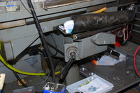
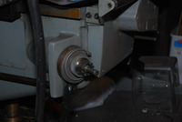
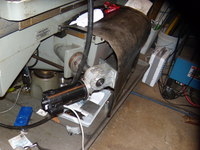
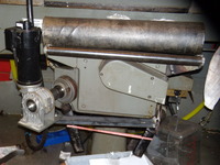
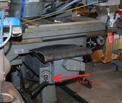
The point of this project is to motorize the knee, that is, replace a crank handle with a DC servo motor so that the knee could be moved with precision and speed. This "axis" is normally called the "W" axis. It would allow me to change tools from short to long, within the same G code program, and not lose the Z offset.
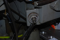
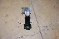
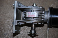
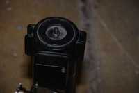
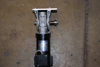
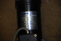
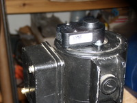
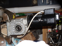
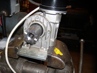
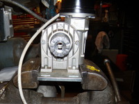
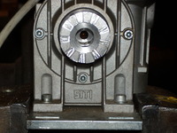
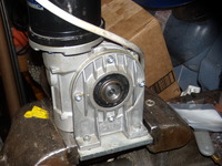
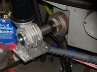
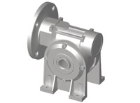
I lucked out and purchased, on eBay, a Soelma Italian made DC motor, with a shaft for encoder in the back, with a SITI "MI 40" gearbox (see drawing below). The price was $41. The DC motor is 65 volts, 3,000 RPM, with 15:1 reduction. It is worm driven. At rated RPM, it would give me roughly 40 IPM speed of the knee, which is great.
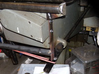
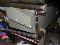
The knee has a pneumatic assist, a pneumatic cylinder pushing it upwards. In essense, this takes off a lot of stress away from the knee screw, and makes the compressed air (air compressor) take most of the physical "work" lifting the knee. This helps with screw wear, as well as requires less torque to move the knee up and down.
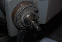
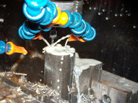
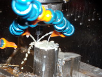
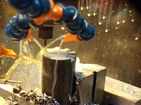
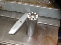
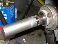
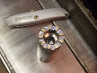
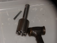
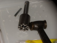
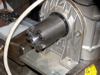
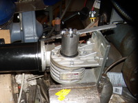
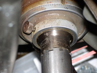
The first part was making a "dog clutch" to engage the same thing on the knee crank. . I made it from a 12L14 steel bar.
The G code to make the dog cultch teeth is here:
(knee teeth)

#<_safez> = 0.03

#<_xc>       = 0
#<_yc>       = 0
#<_milld>    = 0.125
#<hub_diameter> = [5/8+0.02]
#<_radius1>  = [ [1-#<_milld>] / 2 ]
#<_radius2>  = [ [1+5/8] / 2 ]
#<nteeth>    = 9
#<_frate>    = 0.7
#<_thickness> = 0.15
#<cutoff_thickness> = 0.46
#<_d1> = 0.175
#<_d2> = 0.273

#<_zstep> = [#<_milld>/3]


F#<_frate>
G40
S1 M3 M8

G54

O<withdraw> call [#<_safez>]
G0 X0 Y0

G10 L2 P1 X0 Y0 R0

O<withdraw> call [#<_safez>]
G0 X0 Y0


(One pass of one tooth)
O100 sub
  #<z>     = #1
  #<r>     = #2
  #<d1>    = #3
  #<d2>    = #4

  G0 X[#<r> + #<_milld>] Y[#<d2>/2]
  G4 P0
  G0 Z#<z>

  G41.1 D#<_milld>
  G0 X[#<r>] Y[#<d2>/2]
  G1 X0 Y[#<d1>/2]
  G1 Y0
  G1 Y[-#<d1>/2]
  G1 X[#<r>] Y[-#<d2>/2]
  G40

O100 endsub

(One pass of one tooth)
O101 sub
  #<safez> = #1
  #<old_z> = #2
  #<z>     = #3

  #<r> = [#<_radius2> - #<_radius1>]

  O100 call [#<z>] [#<r>]
  [#<_d1>] [#<_d2>]

  (Remove material in the middle)
  g1 y0
  g4 p0
  g1 X[#<r>-0.12]
  g0 X[#<r>+#<_milld>]

O101 endsub


(Does one tooth in many passes)
O102 sub
  O<deepanycut> call [101] [#<_safez>] [-#<_thickness>-0.01] [#<_zstep>]
O102 endsub

(Make the teeth)
O<withdraw> call #<_safez>
O<boltholepattern> call [0] [0] [#<_radius1>] [#<nteeth>] [0] [102]
O<withdraw> call #<_safez>

M2
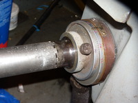
The dog clutch, right after being made, did not want to mesh with the teeth of the knee crank, but it was very close, as intended. After about 10 minutes with a file, the teeth meshed perfectly, with no perceptible backlash.
Tuning of this setup was very complicated. The little gear motor, essentially, has to move a 1,000+ lb chunk of metal, using an ACME screw and a transmission with a lot of "springiness" and friction in it. Eventually, I did tune it so that everything works smoothly. I also had to add a custom HAL component that Andy Pugh suggested on EMC-users mailing list, to turn off power to the servo gear motor 10 seconds after inactivity.
Everything works great now!
