Homemade TIG DC to AC Inverter ==> Prototype 1
 Up
Up
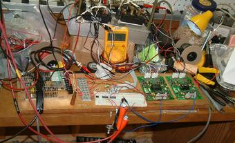
Here you see my first working prototype of the IGBT based TIG
inverter. Again, this is an add on inverter for making Advanced Square
Wave AC from DC supplied by my hobart cybertig welding machine.
Some highlights (see schematic page for component info:
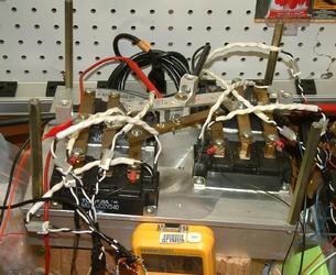
- I used Semikron SKHI 23/12 boards for driving the gates
- I used four Toshiba 200A IGBTs, each of them is a half bridge, so I have two paralleled full bridges with 400 A capacity.
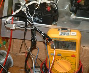
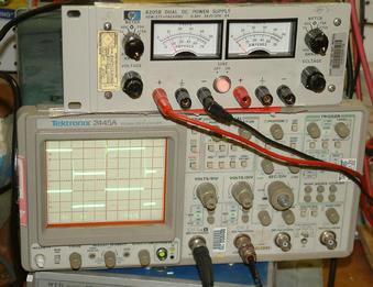
- A regulated current limited DC power supply was used for testing
- No snubber circuit yet
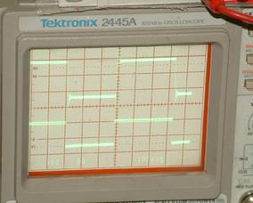
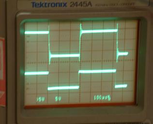
- On the oscilloscope you see:
- top -- voltage across the AC rail. You see some nice ripple caused by the lack of snubber circuitry.
- bottom -- voltage at the gate of one of the half bridges
- My plans include building a robust snubber circuit (I already have all components for a RC snubber), as well as fabricating a sensible enclosure that would fit inside my welder.
- As I intended, no deadtime is seen here (the bridge conducts all the time, there are no transient "dead" intervals, but there are transient shorts).
I feel that this is a nice milestone in my project. I feel that I
have, in principle, proven that I can get to the completion of the
project. All I now need is not to fuck anything up. To that effect, I
should make a nice snubber circuit and err on the side of overbuilding
that snubber. I should manufactore an enclosure that provides proper
mounting, vibration protection and cooling. After that, I should make
sure that front panel controls are properly installed and are
protected from EMI.
(Click on the thumbnail images to enlarge)

 Up
Up


