 Up
Up
Today was a big day for me. I changed my snubber and plugged my prototype into my actual TIG welder.
I was very afraid and wore protective goggles all the time, but nothing terrible happened.
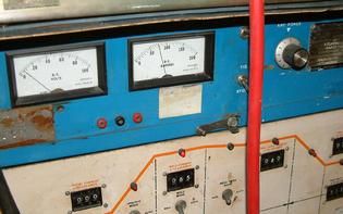
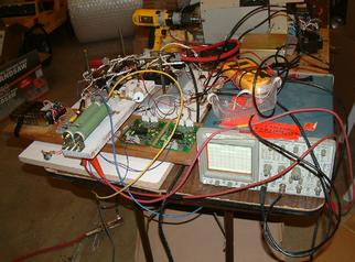
Here you see pictures of my DC -> AC inverter working with my actual Hobart Cyber Tig welding machine.
On the pictures you see the welder running the bridge at 65 amps. The outputs are simply shorted with a 1 gauge cable. No actual welding was taking place. HF arc starting was disabled.
It is quite apparent that whatever I have, in terms of bridge shorting time, as well as the snubber, is working adequately (more on this below). The 150V varistor that I placed across outputs, did not even get warm at 135 amps.
I went all the way to about 135 amperes. The only problem that I has was that the snubber diode got quite warm soon and I had to discontinue the test (reduce amperage to 65 amps).
The bridge seems to be functioning perfectly in a stable manner at 65 amps.
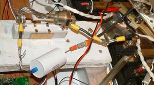
After much experimentation, I realized that the resistor on a simple RC snubber was overheating very quickly and that the capacitor was dumping too much energy when the bridge shorted. I replaced it with an RCD snubber, which you see on the picture 4.
  (I may have gotten the schematic wrong, it is late)


  DC +  -------------------------------+-------|
                                        \      \/ Diode
                                      R /      --
                        BRIDGE          \-------|
                                       ---
                                       ---  Cap
  DC - ---------------------------------|
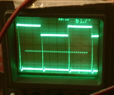
The diode that I used in the RCD is NOT fast recovery. I just do not have a fast recovery diode. That, I think, explains spikes that I still observe. I will probably plop down $25 and buy a 240A diode:
  I want to buy this diode:

  Digikey information:


Technical/Catalog Information 497-4408-5-ND
Standard Package 100
Category Discrete Semiconductor Products
Family Diodes/Rectifiers
Vendor STMicroelectronics
Diode/Rectifier Type Fast Recovery
Voltage-Rated 600V
Current Rating 240A
Package / Case ISOTOP
Packaging Tube
Lead Free Status Lead Free
RoHS Status RoHS Compliant
Other Names 497-4408-5
Let me know if you that that it is wrong for my application.
 |
| Front panel of my cybertig. Shows 65 amps of current. |
 |
| Prototype of inverter. Screwed down to a wood board so that nothing falls off. |
 |
| Top -- timing signal going into the Semikron 23 drivers Bottom -- voltage across the DC rail. You see spikes. at 65 amps, they are about 90 volts. |
 |
| Snubber Circuit -- a big diode, capacitor, and 20 ohm resistor. |