 Up
Up
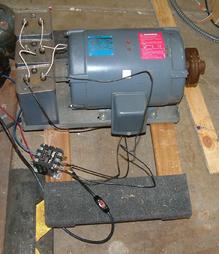
Since the concept obviously worked, I now wanted to go a little bit farther and wire it more properly.
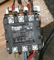
I wired it as follows. I installed a 60 A crcuit breaker in the subpanel. I hard wired the 8 gauge wires with one end into the breaker, and another into the 3 pole definite purpose contactor.
The contactor is a neat thing that, when 110 V is applied to two sensing contacts, with very little current drawn from 110v it closes the big contacts for all three poles.
Legs 1 and 2 of utility 240V were connected to legs 1 and 2 of the motor. Leg 1 (on the motor side, not on utility side) was ALSO connected to one side of the capacitor bank. Leg 3 (the wild, generated leg) of the 3 phase motor was connected to the other side of the capacitor bank. That's how self starting phase converters should be wired according to this excellent article on making homemade phase converters
The converter now would spin up in less than a second. My next task was to measure voltages between legs, which would be suggestive of the actual degree of phase shift. The voltages were as follows: 256 V utility, 239V, and 271V. I did not like it.
I then removed one 92 mF capacitor from the bank, leaving only two capacitors with the total capacitance of 184 mF. The effect of this was that instead of less than a second, the motor would spin up in about one second. Not a big deal to me. The voltages now were as follows: 256 V utility, 240V, and 260V. I decided that I should go with two capacitors.
Costs of parts actually used, so far:
The total cost, so far, is $45. Wires and new breaker do not count.


